1. CAD Design & Engineering Analysis
Key Skills
3D Parametric Modeling, Design for Manufacturability (DFM), Structural Simulation
Core Tools
SolidWorks, SolidWorks Simulation, Manual Machining (Mill, Lathe)
Outcomes
CSWA Certification, flight-tested hardware, and validated analysis reports.
Computer-aided design and finite element analysis form the foundation of modern mechanical engineering practice. This section showcases my proficiency in SolidWorks for 3D modeling, engineering documentation with GD&T, and structural simulation using finite element analysis techniques.
Academic Foundation
My proficiency with these tools is built on a strong academic foundation from the Colorado School of Mines, where practical application is a core part of the curriculum.
- EDNG151: Design I
- Learned the fundamentals of the engineering design process, including teamwork, stakeholder identification, project management, and the basics of SolidWorks modeling.
- MEGN201: Design & Fabrication
- Developed skills in creating detailed engineering drawings, applying GD&T, and translating digital designs into physical parts using manual mills and lathes. This course expanded my SolidWorks abilities and prepared me to earn the CSWA certification.
- MEGN324: Finite Element Analysis
- Applied principles of statics and mechanics of materials to computational simulation. Learned to use SolidWorks Simulations for FEA, interpret results, and create professional engineering reports to document and present findings.
1.1 SolidWorks CAD Modeling
SolidWorks is my primary CAD platform for designing complex assemblies, creating manufacturing-ready parts, and performing analysis. My experience includes parametric modeling, assembly constraints, and design optimization.
1.1.1 Haack Series Nose Cone Design
This CAD project involved designing a Haack series nose cone for my "Wave Function" high-power rocket. The Haack series (or Von Kármán ogive) is an optimal aerodynamic profile that minimizes drag.
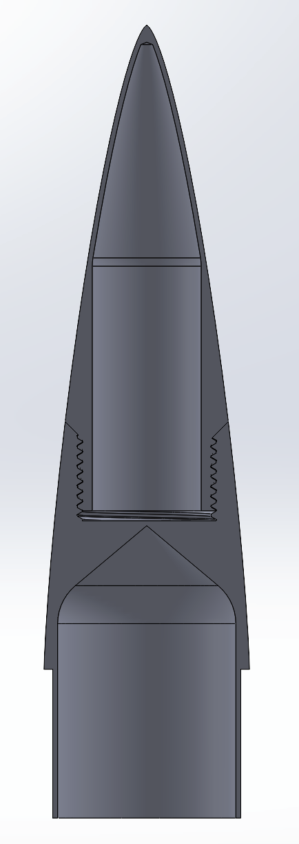
Design Rationale: The nose cone was strategically divided into two parts to accommodate the 220 mm build height of the available 3D printer. This required careful consideration of:
- Joint interface geometry for alignment
- Fastening method (threaded inserts)
- Aerodynamic continuity across the split line
- Structural integrity under flight loads
Technical Specifications:
- Overall length: 385 mm
- Base diameter: 98 mm (4-inch)
- Material: PLA (for 3D printing)
- Wall thickness: 8 mm
The final design was successfully 3D printed, assembled, and flown on November 17th, 2025, demonstrating the practical application of CAD for aerospace hardware.
1.2 Geometric Dimensioning & Tolerancing
Proficiency in GD&T is essential for communicating design intent and ensuring part interchangeability. Through MEGN201, I created engineering drawings with GD&T callouts and then manufactured the parts myself.
1.2.1 Derby Car Chassis
This project involved designing, documenting, and manufacturing a miniature racing vehicle. I was responsible for the detailed engineering drawings and manual machining.
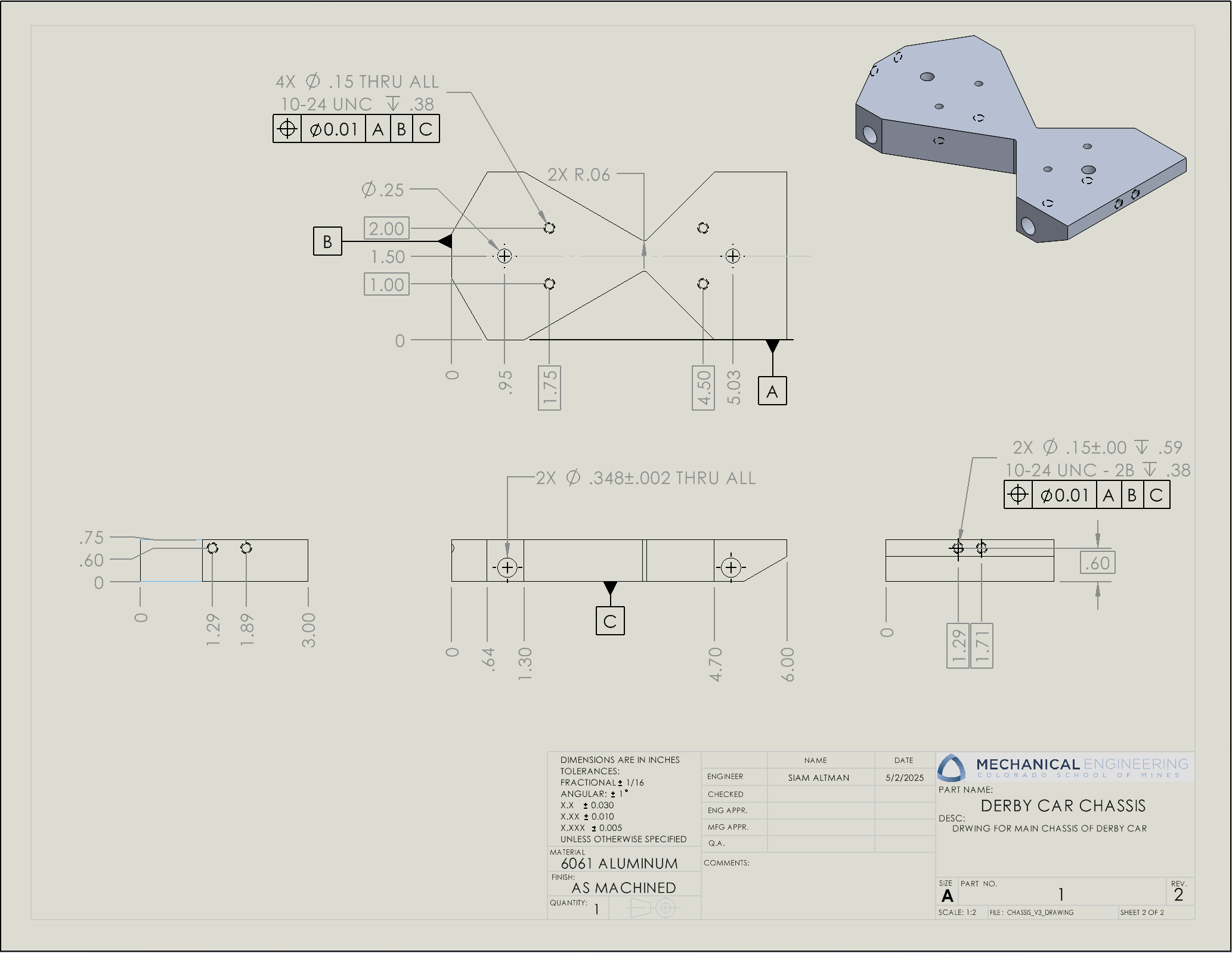
Key GD&T Features
- Positional Tolerancing: Four mounting holes specified with Ø 0.01 tolerance relative to datums A, B, and C for alignment.
- Datum Reference Frame: Established primary (A), secondary (B), and tertiary (C) datums for inspection.
- True Position: 10-24 UNC tapped holes toleranced to guarantee fastener assembly.
Manufacturing Process
- Material: 6061 Aluminum.
- Operations: Primary operations on a Bridgeport-style vertical mill.
- Secondary Ops: Drilling on a drill press and cylindrical features on a manual lathe.
1.2.2 Completed Assembly
After careful machining to correct tolerance stack-up issues, the derby car was successfully assembled. This project reinforced the critical relationship between design documentation and manufacturability.
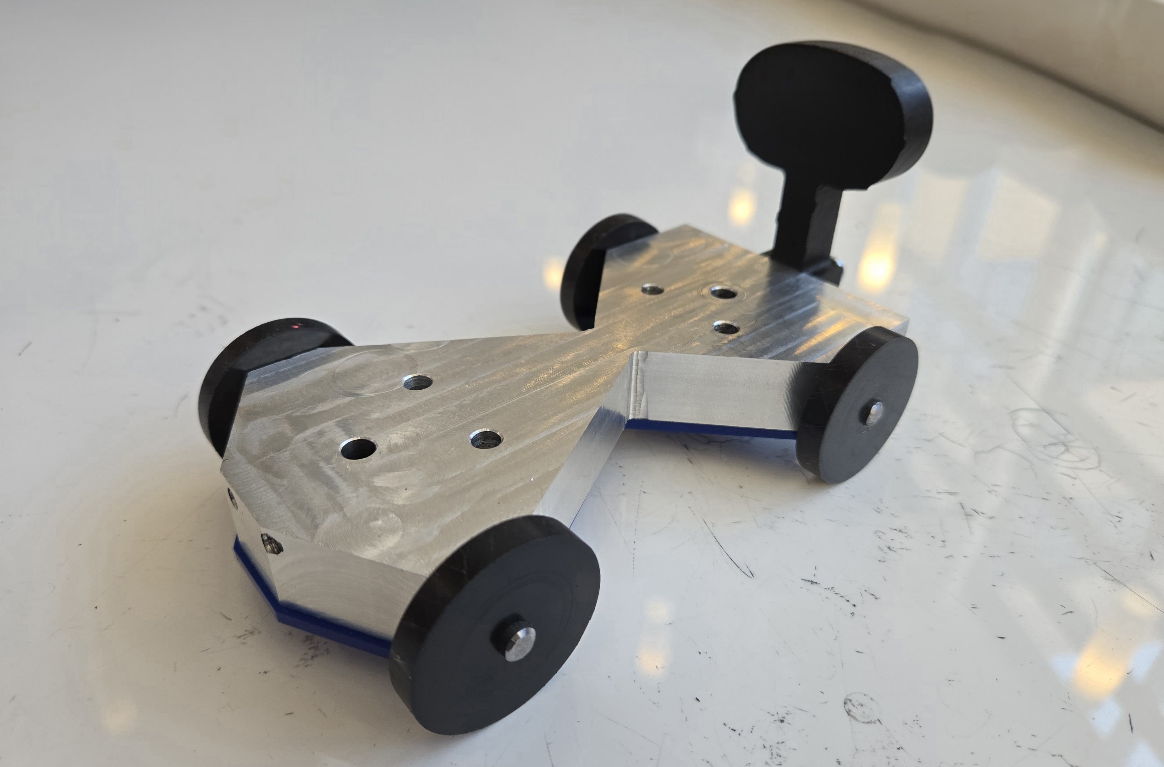
The car achieved 2nd place in a competition competing with 30 other teams during testing, proving that precision in documentation and fabrication pays dividends.
1.3 Finite Element Analysis
FEA is an indispensable tool for validating designs. Through MEGN324, I developed proficiency in SolidWorks Simulation for linear static analysis, mesh refinement, and results interpretation.
1.3.1 Project Overview: Vehicle Suspension Analysis
This capstone project involved a structural analysis of a vehicle suspension assembly to determine stress distributions and validate the design under a maximum cornering force load case.
Loading Conditions:
- Applied forces: 2500 N vertical load, 1200 N lateral load.
- Boundary conditions: Fixed constraint on mounting bracket holes.
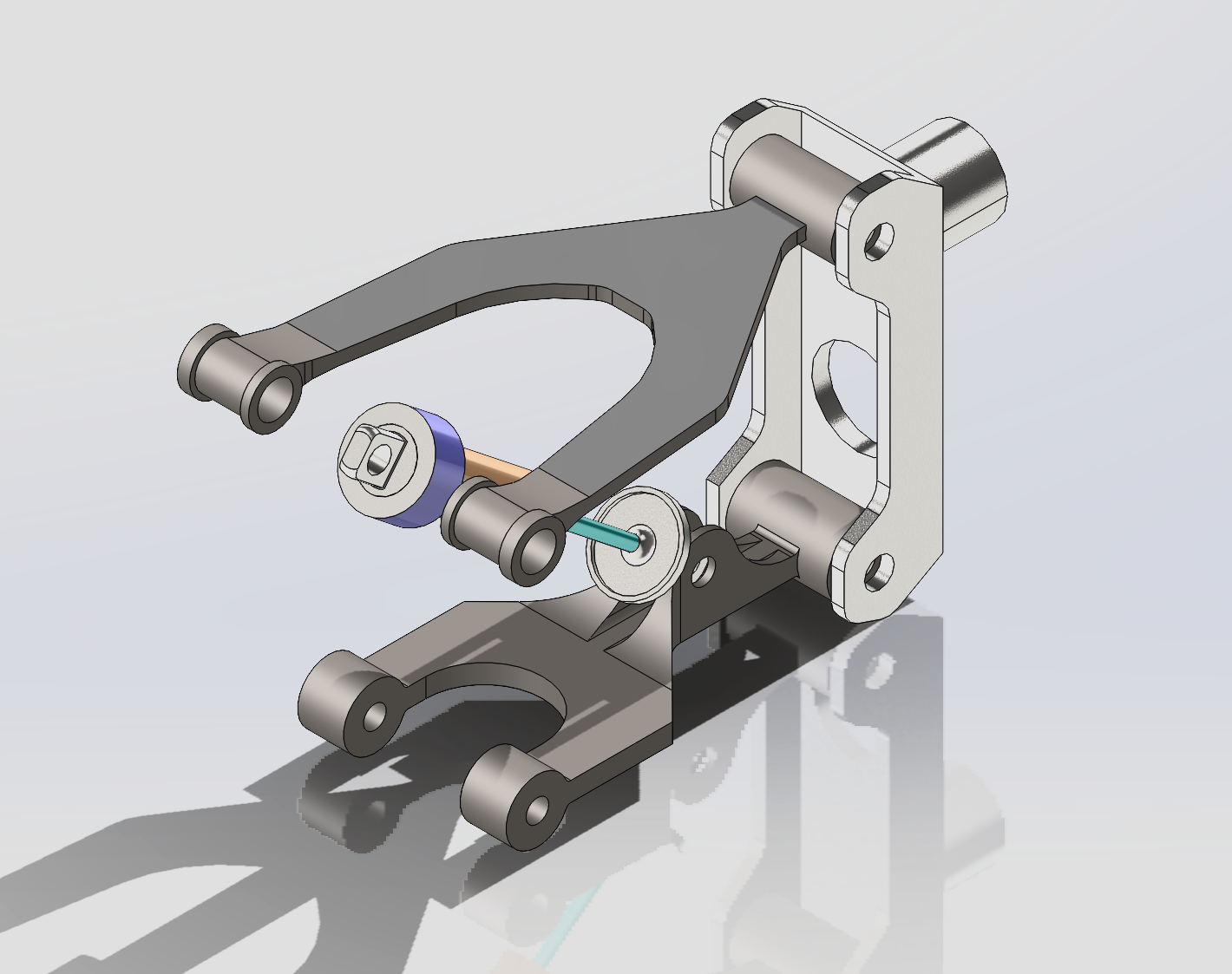
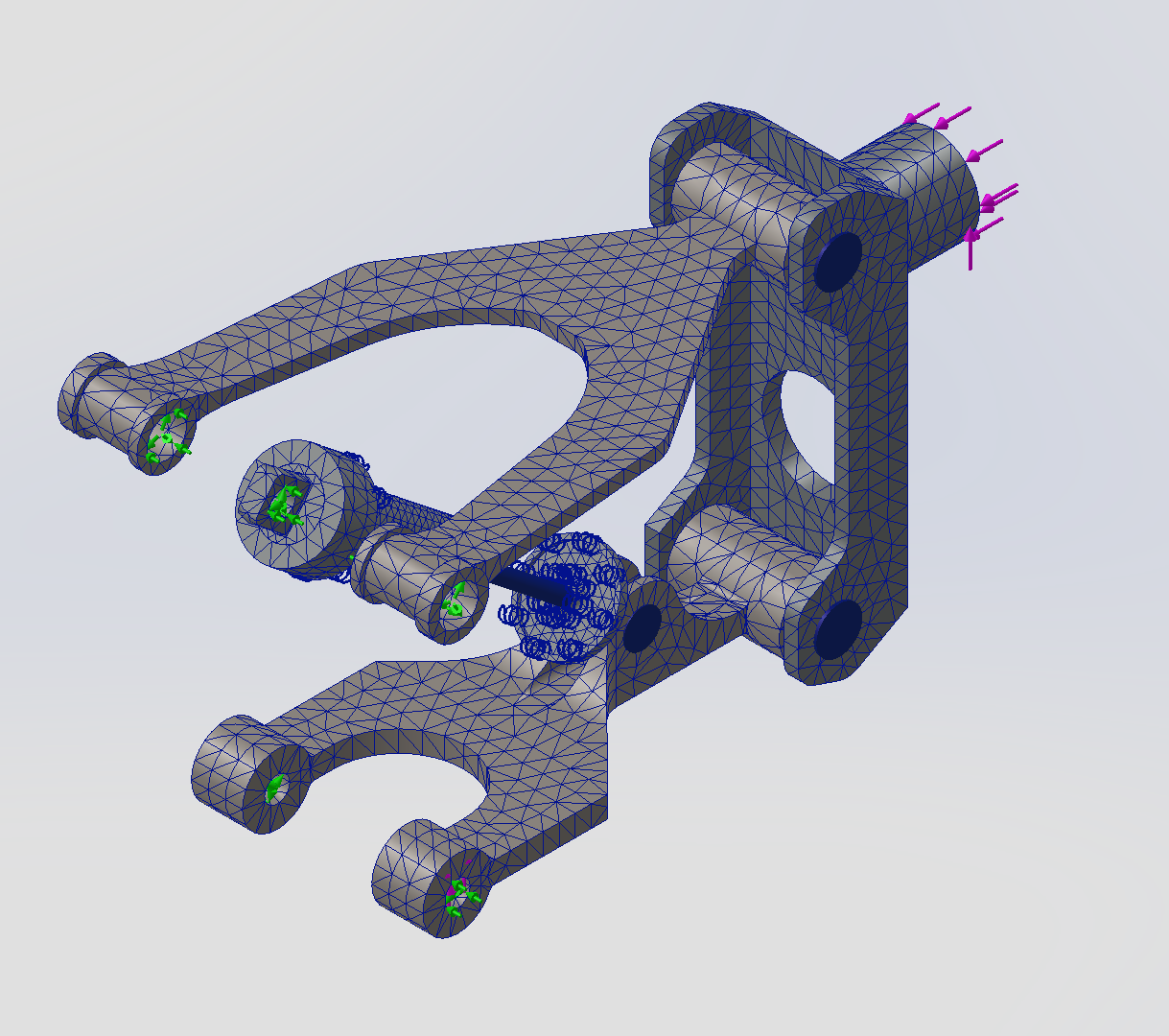
A mesh convergence study was performed using second-order tetrahedral elements to ensure solution independence from mesh density.
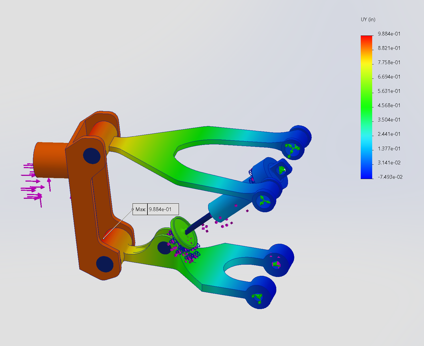
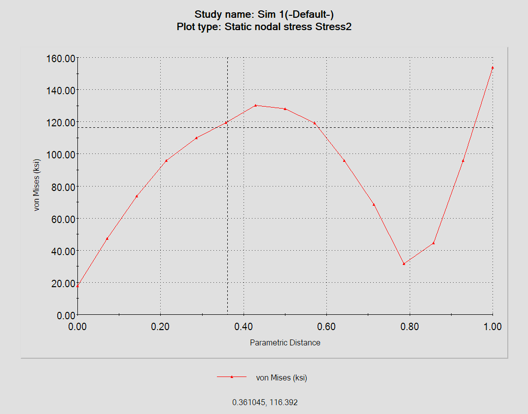
Von Mises stress was used as the failure criterion. The probe plot shows a peak stress of approximately 132 ksi at the upper control arm mounting bracket fillet.
1.3.3 Results & Recommendations
- Material: 6061-T6 Aluminum (Yield Strength = 40 ksi)
- Maximum von Mises stress: 132 ksi (at upper control arm mounting bracket fillet)
- Minimum factor of safety: 0.87
Design Recommendations
Based on the analysis, the following design changes were recommended to reduce stress concentrations and improve the factor of safety:
- Increase fillet radius at mounting bracket transition from 2 mm to 4 mm.
- Add a reinforcement gusset at the high-stress junction point.
- Consider a material upgrade to 7075-T6 aluminum for improved strength.